
Journal trmj's Journal: Senseless (or how to make a better wii sensor bar)
So a common complaint among Wii owners is that the sensor bar cable is too short. I covered this topic in my previous journal, so if you don't know what I'm talking about, reference that.
Pictures are now uploaded.
Getting right down to the details, here's what you need:
1) A whole bunch of resistors
2) A spare DC adapter that's at least 600mA
3) Some PC board
4) A soldering iron
5) Wires
6) A method of cutting the PC board
7) A multimeter
8) Six IR LEDs (transmitters, not receivers)
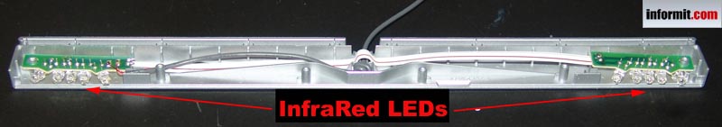
To start with, know what you're imitating. You can see a video of it in action or look at a more detailed picture, or if you have the tools you can take apart your sensor bar. Basically, that annoying wire is only for power and nothing more, which is why we can get rid of it without problem.
Before going to your local Radio Shack or what have you for supplies, check the power adapters you have. Find one with the correct amperage, and check the voltage to know what resistors to pick up. Remember those electrical engineering classes from middle school that you never figured you'd use? Yeah, me either. Luckily, Buffer took some of those classes in college. Bug him if you want to know about the resistors and circuit setup. That stuff is beyond me.
Now, these instructions are a basic guide, not a step by step howto. I will include some notes though, as to why we did what we did. These notes are important because you'll see some differences between your sensor bar and ours. The first of which is that we used 6 LEDs while the original uses 10. This is for two reasons: First, the LEDs we got are high intensity, so we don't need as many of them, and second, because finding a power adapter above 600mA that isn't in use by your router is kind of tough (the LEDs are 100mA each). The one we used was from an ancient computer speaker set by Cyber Acoustics.
Now then! Build your circuit. Remember, you want to power the LEDs without blowing them. This means lowering the voltage with the resistors down to a level that's safe for 6 LEDs to function. If you're sloppy with the solder, it's safe to have an extra 10ish volts. Solder isn't the best conductor, and will impede the flow a tad. You want to have the circuit have both a positive and negative lead on two sides, to power two sets of three LEDs.
Got that finished? Great! Hey, I said this was a guide, not a step by step. Quitcherbitchin. Now wire up three LEDs on a piece of PC board (you can cut these pieces in advance, look at the pictures of our finished product for an idea) and combine the positive leads to one side and the negative leads to another. Hook them up to one side of the circuit. At this point you can test and see if your device works at all by soldering on the power cable and plugging it in. Put your Wii in sensor bar sensitivity mode and point the wiimote at your IR setup. If you see a dot on the screen, you've done something right. If you see three dots, you're either holding the wiimote too close or your LEDs are too far apart. Check it against your original sensor bar for an idea of what it should look like.
If all works well, get the other LEDs mounted and wired. You can now use electrical tape to mount the setup or encase it in something nice, but all you need is a nearby outlet. No more having to string the sensor bar wire across the room just to shoot a bow in Zelda.
Pictures are now uploaded.
Getting right down to the details, here's what you need:
1) A whole bunch of resistors
2) A spare DC adapter that's at least 600mA
3) Some PC board
4) A soldering iron
5) Wires
6) A method of cutting the PC board
7) A multimeter
8) Six IR LEDs (transmitters, not receivers)
To start with, know what you're imitating. You can see a video of it in action or look at a more detailed picture, or if you have the tools you can take apart your sensor bar. Basically, that annoying wire is only for power and nothing more, which is why we can get rid of it without problem.
Before going to your local Radio Shack or what have you for supplies, check the power adapters you have. Find one with the correct amperage, and check the voltage to know what resistors to pick up. Remember those electrical engineering classes from middle school that you never figured you'd use? Yeah, me either. Luckily, Buffer took some of those classes in college. Bug him if you want to know about the resistors and circuit setup. That stuff is beyond me.
Now, these instructions are a basic guide, not a step by step howto. I will include some notes though, as to why we did what we did. These notes are important because you'll see some differences between your sensor bar and ours. The first of which is that we used 6 LEDs while the original uses 10. This is for two reasons: First, the LEDs we got are high intensity, so we don't need as many of them, and second, because finding a power adapter above 600mA that isn't in use by your router is kind of tough (the LEDs are 100mA each). The one we used was from an ancient computer speaker set by Cyber Acoustics.
Now then! Build your circuit. Remember, you want to power the LEDs without blowing them. This means lowering the voltage with the resistors down to a level that's safe for 6 LEDs to function. If you're sloppy with the solder, it's safe to have an extra 10ish volts. Solder isn't the best conductor, and will impede the flow a tad. You want to have the circuit have both a positive and negative lead on two sides, to power two sets of three LEDs.
Got that finished? Great! Hey, I said this was a guide, not a step by step. Quitcherbitchin. Now wire up three LEDs on a piece of PC board (you can cut these pieces in advance, look at the pictures of our finished product for an idea) and combine the positive leads to one side and the negative leads to another. Hook them up to one side of the circuit. At this point you can test and see if your device works at all by soldering on the power cable and plugging it in. Put your Wii in sensor bar sensitivity mode and point the wiimote at your IR setup. If you see a dot on the screen, you've done something right. If you see three dots, you're either holding the wiimote too close or your LEDs are too far apart. Check it against your original sensor bar for an idea of what it should look like.
If all works well, get the other LEDs mounted and wired. You can now use electrical tape to mount the setup or encase it in something nice, but all you need is a nearby outlet. No more having to string the sensor bar wire across the room just to shoot a bow in Zelda.

Senseless (or how to make a better wii sensor bar) More Login
Senseless (or how to make a better wii sensor bar)
Slashdot Top Deals